Fomu EVT: Prototype or Business Card?
When starting a project from scratch, it’s important to create prototypes. For programming, you usually create small snippets that demonstrate what you want. Fortunately, software is quick to compile, so you’re free to create hyper-specialized programs that exist only to test out particular theories. With hardware, the build cycle is much longer and more expensive, so test widgets must examine multiple theories in one build, and should be as flexible as possible.
Fomu EVT manages to filfill three different roles:
- Schematic validation
- Firmware debugging
- Project prototyping
Schematic Validation
When designing Fomu, there were several questions that needed answering. For example, I wasn’t sure what sort of oscillator to use – a MEMS oscillator would be smaller, but it could also be more expensive and not have many second sources. Nor was I sure what sort of regulator to use – the reference manual suggested a noise filter for VCCPLL, but an actual regulator could be cleaner, smaller, and cheaper. In order to answer these questions, I needed to build a prototype board.
In the schematic, there are multiple places where I’ve specified components are “DNP”, or “Do Not Populate”. Here are the two oscillators:
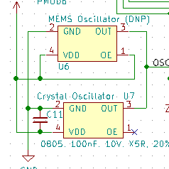
If it turns out that the oscillator that I’ve selected is no good for some reason, I can simply remove the old one and solder the alternative in place. Notice how they share a decoupling capacitor – normally you wouldn’t want to do that, but if you place the two options close enough together on the PCB, then the one decoupling capacitor can serve either part that’s populated.
Another choice that was validated was the PLL voltage source. The reference manual suggests a simple RC filter network, but tiny capacitors can be surprisingly expensive. The thought was to feed VCCPLL directly from its own 1.2V regulator instead of slaving it off of the main 1.2V regulator. However, both options were left on the schematic:
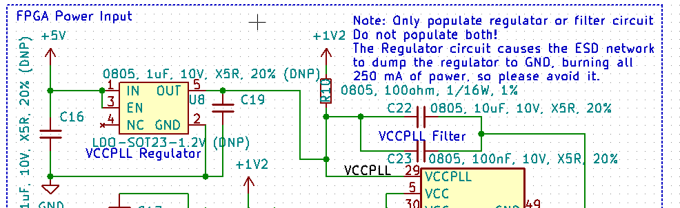
As you can see from the schematic note, the ICE40 didn’t much like being fed by a regulator. The FPGA got very hot at ~60C, and the regulator ended up drawing its maximum rated 250 mA. The FPGA worked just fine, but it’s not an optimal configuration, so future versions of the FPGA switched to using the filter network.
Firmware Debugging
Fomu EVT is designed to operate as a Raspberry Pi hat. This means that it connects directly to a Raspberry Pi and maps those pins to something useful. For exmaple, the UART pins are wired up to the FPGA, and the 5V line on Fomu EVT is connected to the Raspberry Pi 5V line.
The SPI pins on the Raspberry Pi are connected to the SPI pins on the FPGA and the flash chip, though curiously this turned out to be less useful than you’d think. SPI has a concept of a “Master” and a “Slave”, and the Raspberry Pi has pins labeled “MISO” (Master In, Slave Out) and “MOSI” (Master Out, Slave In). These are where data flows into and out of the Raspberry Pi, respectively. Because the SPI flash chip is a slave, you connect the Raspberry Pi MOSI to the flash chip MOSI, and the Raspberry Pi MISO to the flash chip MISO.
Except for the FPGA. When the FPGA self-boots, it’s a master, so you’d connect its “MISO” and “MOSI” pins in the same way. However, when the FPGA is booted by another device it becomes a slave. Its “MISO” pin becomes “MOSI”, and the bus effectively flips around. The Raspberry Pi doesn’t have the ability to flip its MOSI and MISO pins, so we’re out of luck.
This, combined with the fact that Linux SPIDEV doesn’t support quad spi, led me to write Fomu Flash. It uses bit-banged calls to send SPI commands to both the FPGA and the SPI flash chip. It can work in one-, two-, four-, or quad-spi mode. It is capable of putting the FPGA into reset to talk to the SPI flash chip, or resetting the SPI flash chip to talk to the FPGA. It is a fantastic tool for development because it is so fast, and will come in very handy both in firmware development in the future, as well as on the factory floor for manufacturing.
Additionally, the UART is incredibly handy for debugging, because it gives immediate feedback to what’s happening on the softcore CPU.
We may use the excess debug pins for something else, such as a simple shift register to access the wishbone bus, but so far there isn’t anything available to take advantage of these pins. Still, they were relatively easy to add, so I made sure to attach them.
Project Prototyping
We haven’t gotten to the point of project prototyping, but the idea is still there. The captouch pads could prove useful, and the RGB LED provides good feedback.
EVT2 has one PMOD header, and EVT3 has two. This standard makes it easy to incorproate third-party accessories such as accelerometers or sensors, or even fancier things like Ethernet.
In the Prototyping mode, Fomu EVT is designed to run without a Raspberry Pi. This is similar to how the final release of Fomu will work, completely untethered from its host controller. Fomu EVT is designed to make it easy to go “Hey, look at this!” and connect it to a host PC.
We’re not yet at the point where Fomu EVT is useful for prototyping; It’s still helping us develop the firmware. We’ll be at this phase in a few months, as we finalize the firmwre for Fomu.
Fomu EVT as a User Test
Most products have pre-release hardware that looks nothing like the final version, has extra features that get shaved off, or behaves differently. By building the PCB larger, we can try out different part options, and have it connect directly to debug pins for firmware development. With the extra room, we can give additional expansion options in the form of debug headers.
Fomu EVT is proving to be a very useful testbed for trying out hardware, firmware, and software options. It’s gotten us quite far, and now I look forward to seeing what cool stuff comes out of the discoveries we’ve made working with it.