Palawan DVT1 Build
I’ve just finished taping out Palawan DVT1. This is the first build in a long time, and is a rather heavy redesign. The three biggest changes are:
- New CPU/Radio pair
- 433 MHz operation
- Redesigned in KiCad
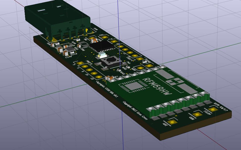
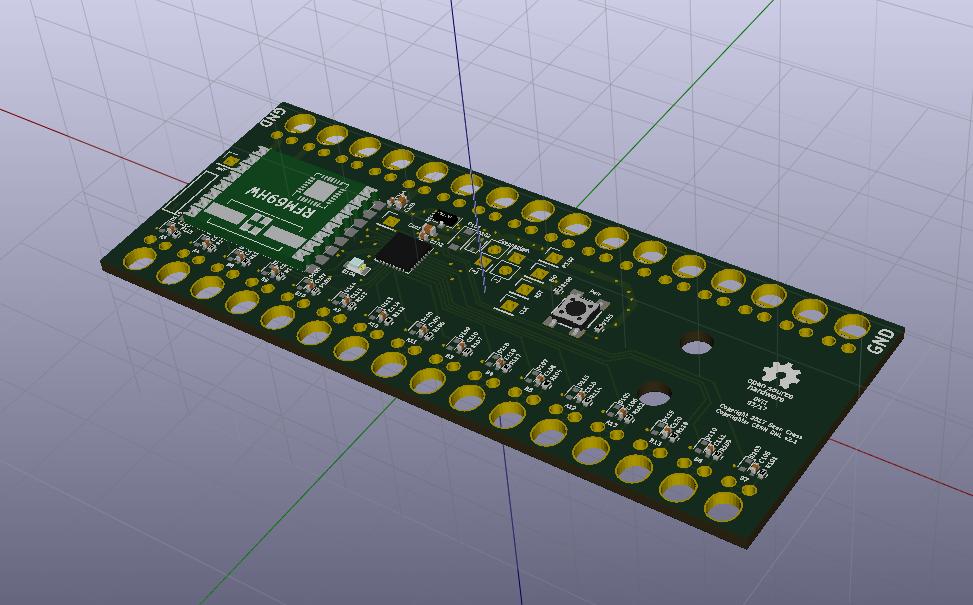
KL02 and RFM69HW
Previously, Palawan was based on a Freescale KW01. This two-in-one chip functioned as both the radio and the processor. This worked well, and enabled one chip to do the work of two.
The KW01 part is becoming challenging to find. It’s still in production, but prices are creeping up and availability is scarce. It is not the sort of thing one wants to build a new project around. So out it goes.
Instead, the design uses a KL02 as its CPU and an RFM69HW module as the radio. The KL02 is a much simpler part, but still operates at 48 MHz meaning Grainuum can still be used. The RFM69HW is a module that happens to have an identical radio register set to the KW01, meaning software will be able to Just Work. Additionally, all of the analog circuitry is built into the module, making assembly much cheaper.
433 MHz
The system is designed to work at 433 MHz now. Previously, it used the 900 MHz band. Unfortunately, 914 MHz is only usable in the Americas, while 868 MHz is only usable in Europe. In Asia, neither of these bands are allowed. To meet the needs of all three, the new design uses 433 MHz.
The new pair of boards use a coil antenna. It remains to be seen how reliable this antenna is, but it ought to work just fine.
KiCad Design
The other major change is that the board is done in KiCad now. KiCad has matured into a fantastic piece of software. The 3D view is very useful, and there are all sorts of wizards to do things like footprint generation. Even better, there is a wide community of open-source libraries in existence already, making board design that much easier.
Both boards were sketched and laid out over the course of one day total. Another day or two was spent tweaking things, improving power routing, and setting out assembly diagrams just so. But KiCad makes all of that simple, and preexisting libraries are a fantastic resource.
User Experience Redesign
While redesigning the board, I also took the opportunity to fix some of the user experience issues. The biggest drawback from the previous board was the lack of ground points. In this board, I’ve set aside the entirety of one edge to act as ground points.
Another shortcoming was the design of the alligator clip points themselves. In this redesign, I’m going to try leaving only one hole for the alligator clip, and use the edge of the board to act as the other. This will save on cost and make it easier to use.
Previously there was a “mode” switch. The exact nature of this switch was never determined, so the switch was dropped in favor of more I/O ports.
Similarly, since the new chip has no capacitive input, all inputs are strictly digital. This simplifies the user experience by quite a bit, since there is now only one mode possible.
I also learned a valuable lesson: Label everything, and make it easy to use. Label what ports do what, which pins go to which lines, and where the debug headers are. Also, debug headers are now 0.1" holes rather than 0.05" SWD headers. It’s much easier to find a Raspberry Pi to program these boards than it is to find a specialized SWD tool.
Finally, there is no crystal on the transmitter board. It doesn’t need to be high-speed, so it will simply rely on the internal RC-oscillator. This will save cost and power. The USB stick still has a crystal to ensure it runs at 48 MHz, though it may be possible to rewrite Grainuum to operate at 32 MHz and use the RFM69HW as a clock source. That will be a job for a cost-down later on.
Now I’ll try to get this thing built, and see where to go from here.