Tomu Plastic Case Part 2: PCB Modifications
When designing a plastic case, it is important to work within the limitations of the medium. The design process begins with the PCB, which must fit within the final design space and still be manufacturable. You must take into account manufacturing tolerances and design specifications, while still providing plenty of margin for mistakes.
Tomu is a USB device, and therefore must fit into a USB slot. Section 6.5 of the USB 2.0 specification deals with mechanical details, and is a huge help when designing what amounts to an intelligent USB plug. You might want to print out Section 6.5 and label the missing dimensions for easy reference. You’ll be referring to them a lot.
A case does more than simply protect the electronic components; it affects how the user interacts with the product, and directly affects the user experience. In designing the case, there were three major issues I wanted to address: Horizontal slipping, case center alignment, and permanent case installation.
Standardizing PCB Thickness
The initial Tomu PCB had a varying PCB thickness. If your PCB is thick enough, you can use the PCB + CPU height to wedge the PCB assembly into the slot. This is great for prototyping, but isn’t so great for production products – you don’t want exposed circuitry to sit inside a metal USB port.
Early on I decided to fix the PCB thickness at 0.6mm. This is the maximum thickness I would be comfortable with, because the case needs to cover the PCB as well as the CPU. If the PCB were 0.8mm thick, then there wouldn’t be enough material on top of the CPU, and a gap would form.
Several prototype cases were printed on our Form2 printer, and all cases designed for an 0.8mm PCB ended up with square cutouts on the top of the case due to not enough material.
By standardizing on 0.6mm PCB thickness, we give ourselves enough margin to allow cases to work when produced on SLA and FDM 3D printers, as well as through injection molded tooling.
Horizontal Slipping
When placed inside a case, it’s natural to treat the case + device as a single object. That is, you don’t want to think about the mounting of the case or the angle of the PCB, you want the whole thing to be a single unit to be inserted into the computer. When a lightbulb dies we’re shocked or annoyed because we suddenly have to decompose the concept of a lamp assembly into “fixture” and “bulb” components, and replace the bulb. Similarly, if a PCB falls out of the case when removing it, we’re prone to become frustrated, angry, or simply annoyed at the mental decomposition.
The first case design was mostly a plug that fit into the port alongside the Tomu PCB. This required the user to manually align the two, and the design was prone to leaving the case behind in the port when the device was removed. On the upside, the case was trivial to produce on commodity home 3D printers, which made it a great first draft.
The workaround is to introduce a notch into the PCB that the case can grab onto. That way, when you push the assembly into the port, they move as one. Similarly, the individual components can’t slip out of the USB port separately. Adding notches is one step towards combining components into an assembly.
Tomu v0.3 contained a first attempt at adding a notch that a case could grab onto. In fact, v0.3 added two 0.5mm notches. Unfortunately, things tend to look much bigger on the screen than in real life, and the notches ended up being too small to be useful. In fact, because the notch requires a small drill bit, some PCB manufacturers charge extra as the small notch may cause them to break lots of bits. Some prototype 3D cases were made using a Form2 SLA machine, but the notches were just too small to allow usable cases to be printed on traditional FDM printers (about 0.4mm if you’re lucky), or to work with traditional injection-molding tolerances (roughly 0.8mm for consistency and load-bearing parts). The fact that the notch was rounded instead of square was a good choice from a manufacturability, it just needed to be bigger.
The PCB was redesigned for v0.4 in order to address these issues. The notch was enlarged to 1.6mm and moved to only one side of the board. This brought it to within tolerances for both traditional FDM printers and injection molding, and gave us an additional bonus in that the PCB was no longer symmetrical at all. By placing the notch on one side only, it becomes impossible to install the PCB upside-down. Additionally, because the notch is a negative space, a case designer could decide to omit the tab to fit in the notch, and the case would still work.
With the addition of a large, single-sided notch on the PCB, the horizontal slipping problem was effectively solved.
Case Center Alignment
USB ports are rectangular, and it’s sometimes difficult to know which way is up. I have an SD-to-USB adapter that can fit into the port upside-down, but since it only has pins on one side it won’t work at all. This has been the source of a great deal of confusion in the past, and is a thing I wanted to avoid with the new case.
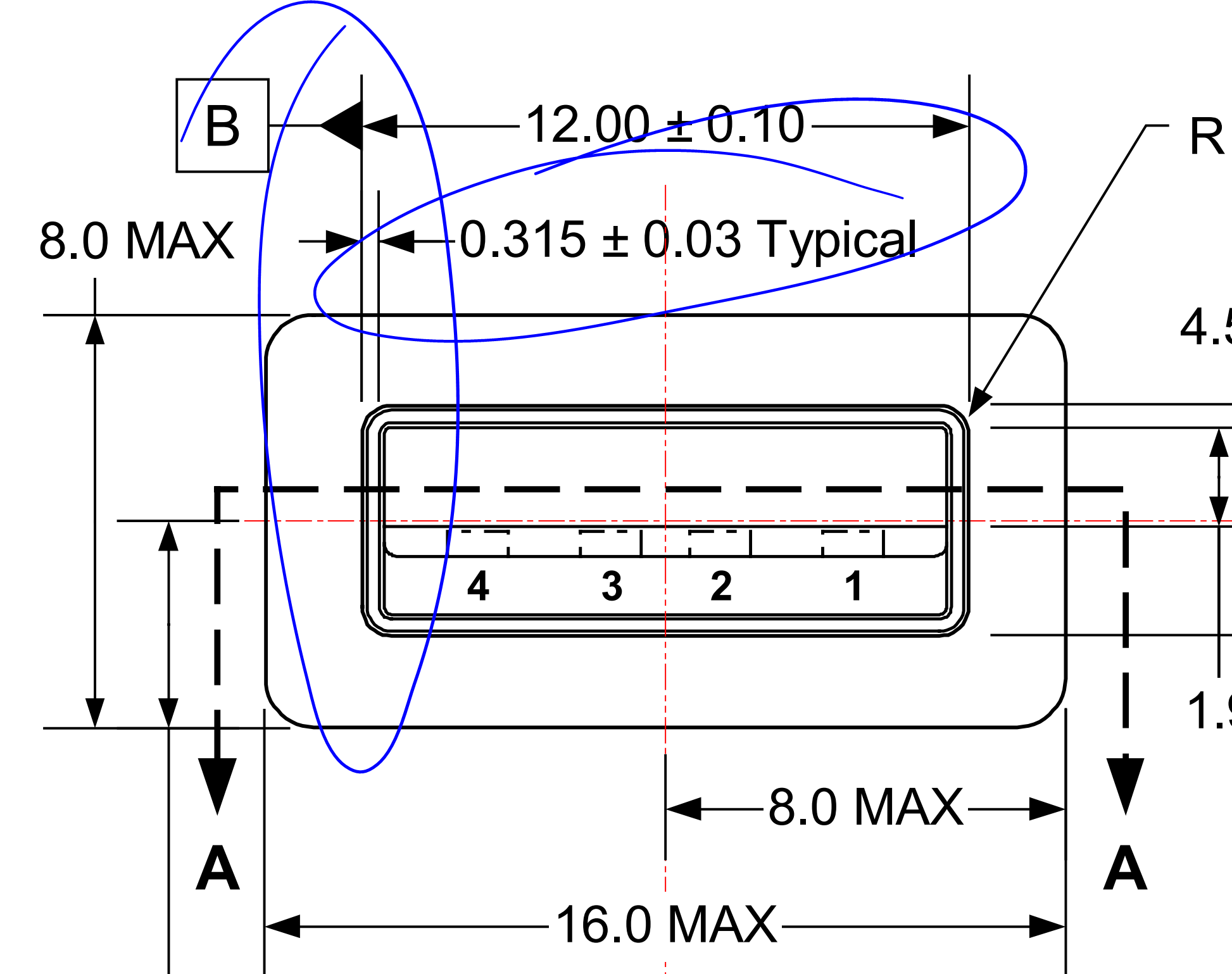
I’ll go into more detail on the mechanics of selecting the dimensions for the guiderails, but one of the concerns I had was snapping off the rails themselves. USB ports are 12.5 +/- 0.10 mm wide, and the original Tomu PCB was 11mm wide, leaving 0.7mm on each side for the case. I printed out several cases on a fancy Form2 SLA 3D printer, and discovered that even with the tight tolerances with SLA, the case didn’t fit well. Worse, the tall walls were not structurally sound, and tended to bend easily.
To solve this problem, I reduced the width of the PCB to 10mm. The result of this change means we can put more case material around the PCB, which reinforces the walls of the plastic case. It also means the case will work better for FDM printers, and the PCB itself won’t slide around nearly as much.
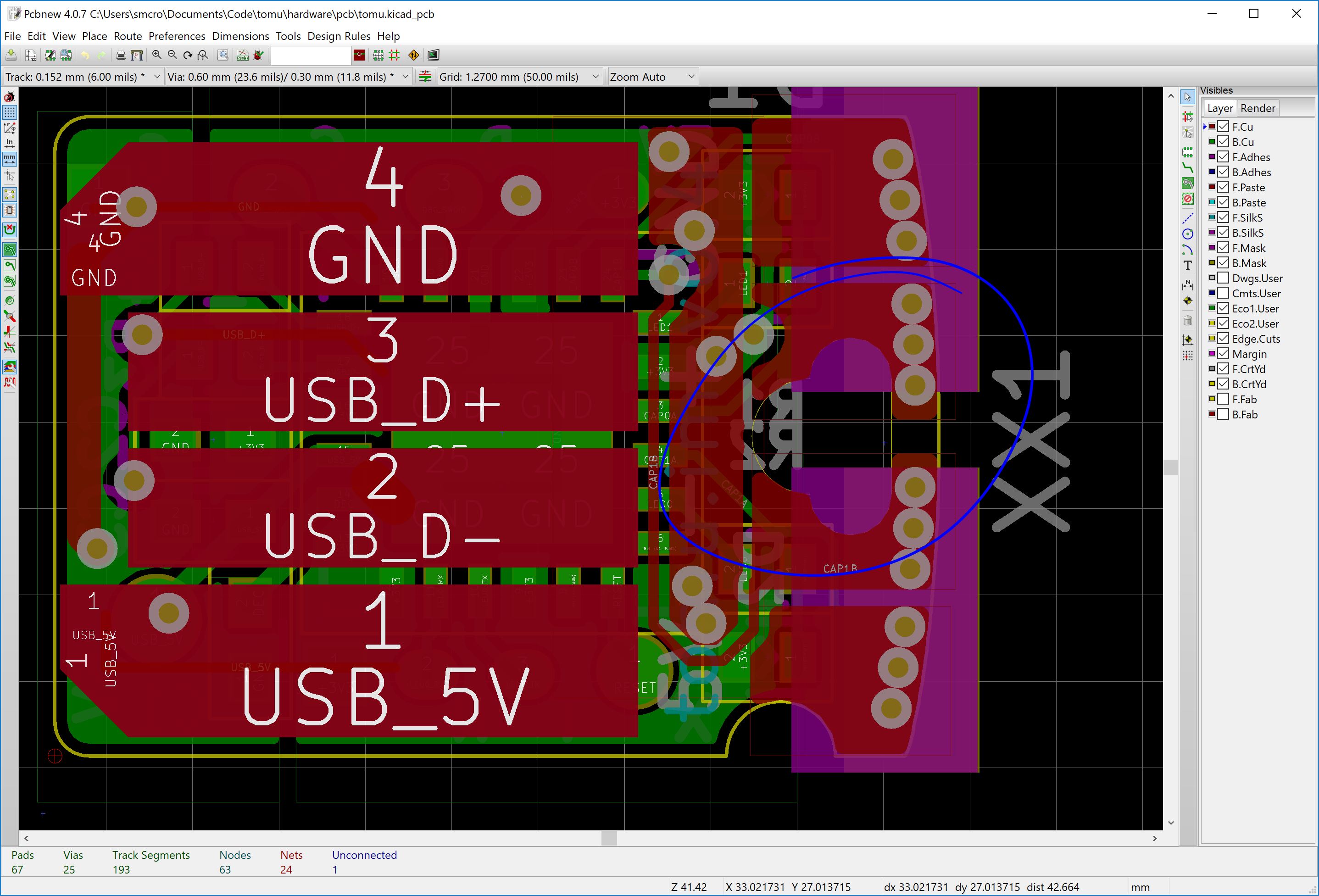
Between the narrowing of the PCB and the increasing of the notch, the PCB components had to be redone. Some traces were made bigger, some pads were made smaller, and I brought out the Reset signal to a test pad making bootloader development easier.
Permanent Case Installation
With alignment issues solved, I decided to tackle the problem of how to keep the assembly from coming apart. It would be nice to think of Tomu as one assembly, rather than separate “PCB” and “case” components. Tim’s original design had a small hole cut into the edge which was designed to allow users to hang Tomu on a lanyard, or use tweezers to pull Tomu out of a PC.
When redesigning the PCB, I thought it would be neat to permanently fix the PCB into the case using heat staking. you may have seen this on cheap toys, where the manufacturer uses a hot iron to melt plastic pegs down into rivets that hold the PCB in place. Such a process is very cheap, because it doesn’t require any components aside from a heat staking jig, and the plan was to let the end user do the heat staking themselves.
In order to do this for Tomu, the hole needed to be enlarged by quite a bit to allow a peg of sufficient size. There weren’t any major issues to doing this, aside from making sure the traces on the PCB weren’t to close to the cuts. Components on the edge of the board were rotated, because between the narrowing of the PCB and the increasing of the mounting hole, space started to become a premium.
As an added bonus, the peg would make doubly-certain the PCB didn’t slide around, and work in tandem with the alignment slot to ensure users assemble the board correctly.
Modifications Complete
By narrowing the PCB, adding a single large slot, and increasing the size of the mounting hole, I made it easier to mate the Tomu PCB to a hypothetical case. There was some back-and-forth iterations to try and get the features just right. The v0.3 PCBs released at LCA2018 were a good test, and validated that 0.6mm PCBs were acceptable. In the next article, I’ll discuss FreeCAD and the steps I took to actually design the case.