Love-to-Code Debug Shoe
Looking to debug your Chibitronics Love-to-Code board, but don’t want to solder on headers? If you have access to a 3D printer, grab the LtC Debug Shoe, print it out, and crimp on some tinned wires. Read on to learn more about the project.
I’ve been working lately on the Chibitronics Love-to-Code project, where we allow users to program a board via audio. To keep file sizes down, the LtC board has an extensive operating system, which means it’s a complicated beast. Well, as complicated as you can get in 21 kilobytes of data.
Debugging this project has been a challenge. I usually use a Raspberry Pi running OpenOCD in order to debug such projects, but the challenge comes in figuring out how to physically connect to the board. Early models had standard 0.1" headers that could be easily connected, but with later iterations those headers were turned into mere pads. Factories build test jigs that use pogo pins to temporarily hit these pads. For day-to-day hacking, the only solution was to solder wires directly onto the pads.
I took this opportunity to learn how to use FreeCAD to prototype and eventually 3D print a “debug shoe” that can be used to easily and quickly debug a board in the field.
This is the result:
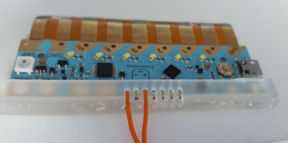
The leftmost pin in the picture is SWD_CLK, and the other wire is connected to SWD_DIO. These are the only two “required” pins for the ARM Single-Wire-Debug protocol. 5V and GND are also necessary, but they’re nicely provided by the programming cable.
To use this, it is necessary to tin the wire, bend it over, then insert it into the top of the grille. The side of the grille is slightly too small, which forms a cleat that holds the wire in place.
Earlier attempts didn’t have the cleat idea, and relied on pure force to make contact. This was very unreliable, and scratched the boards quite a bit.
In contrast, this approach worked on the first time, allowing me to reflash the operating system and load some code.
To use, connect the SWD_DIO signal to GPIO24 (pin 18 on the Raspberry Pi header), and the SWD_CLK signal to GPIO25 (pin 22 on the Raspberry Pi header). Finally, install and run OpenOCD:
openocd \
    -f interface/raspberrypi2-native.cfg \
    -c "transport select swd" \
    -f target/kx.cfg \
    -c init \
    -c "kx.cpu configure -rtos ChibiOS" \
    -c "reset halt"
Now you can connect GDB to debug your board. Run “target remote [pi-address]:3333”, and away you go.